 fullempty.sh

At the end of June, I picked up a Siemens 100A Teleprinter. This model is typically named the "T100" or "Teleprinter 100", or a collection of german words I won't pretend to be authoritative in using here. It's a 5-bit ITA2, or Baudot-Murray encoded machine, using a 40mA current loop for communications.
![]()
The manual for this machine places it firmly as a European product, wired for 220V, and so on. The model I have, which is listed as 100A on the badge, has a 110V motor, yet has a European-style AC connector, and a German-style Ado8 connector, which was used until the 80s for non-phone devices, such as teleprinters and fax machines.
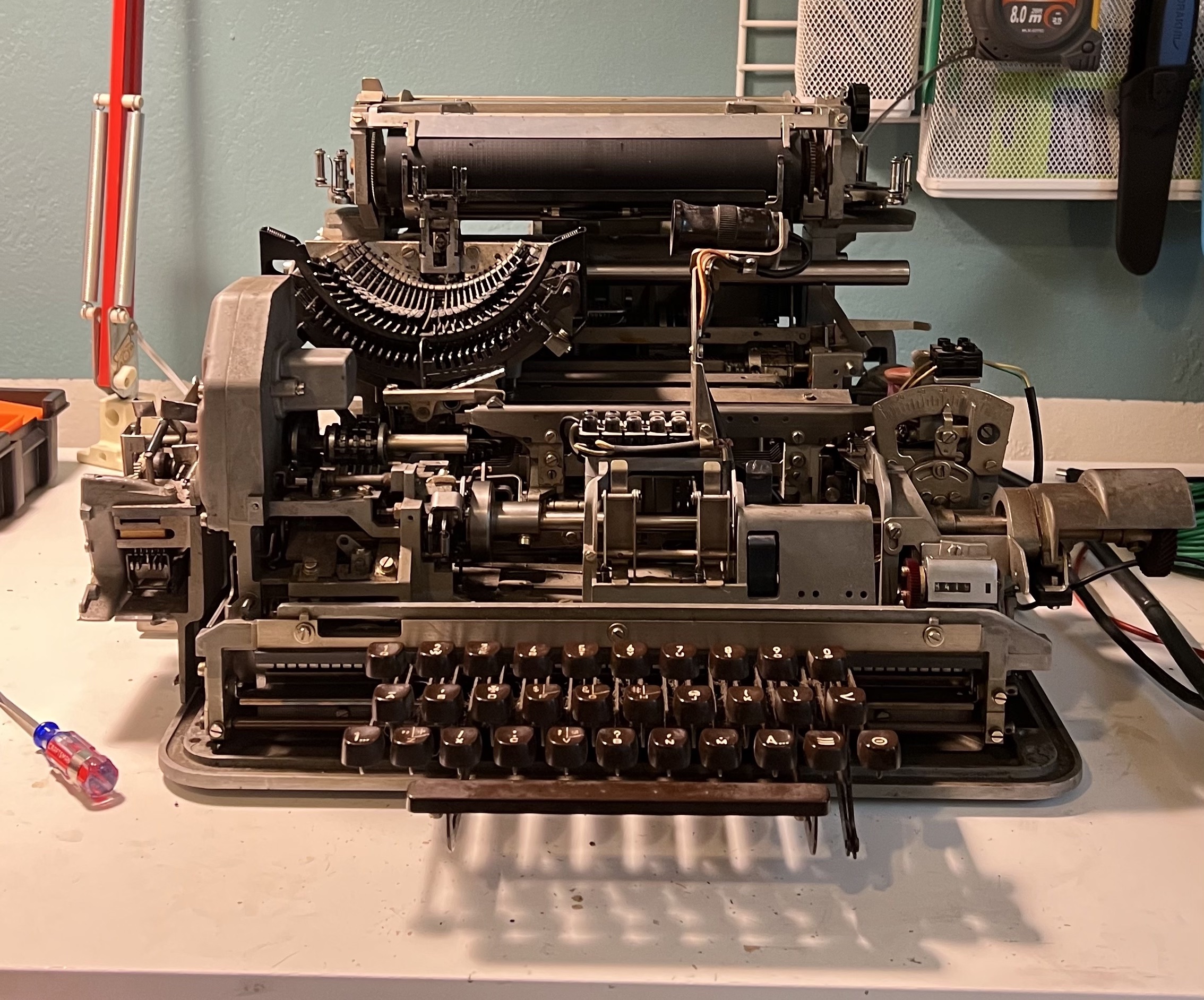
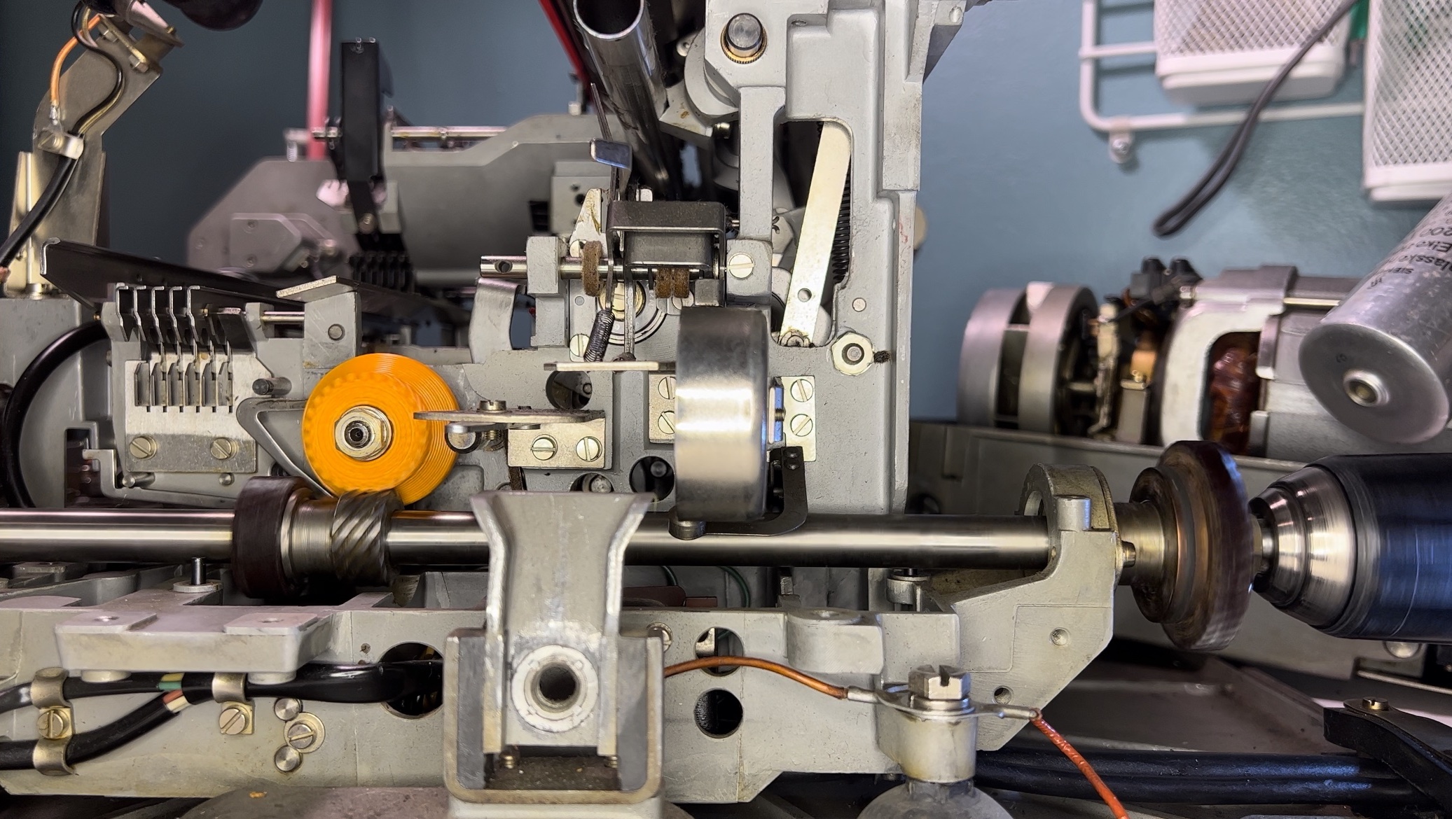
The insides were about as greasy as you'd expect for an electromechanical device that is heavy on the mechanical. At first, I bought a couple of buck-boost converters off Amazon to provide the 80-120V voltage for the current loop, using a couple of 5W resistors to limit to the current to roughly around the 40mA needed. Teleprinters need a current loop present to run "closed", rather than "open". In this case the Siemens 100A has a gear and clutch body that interfaces with a helical gear on the main driveshaft, and if the current loop is present, the "receiver" will engage its electromagnet, causing the clutch to release and not drive the "printer".
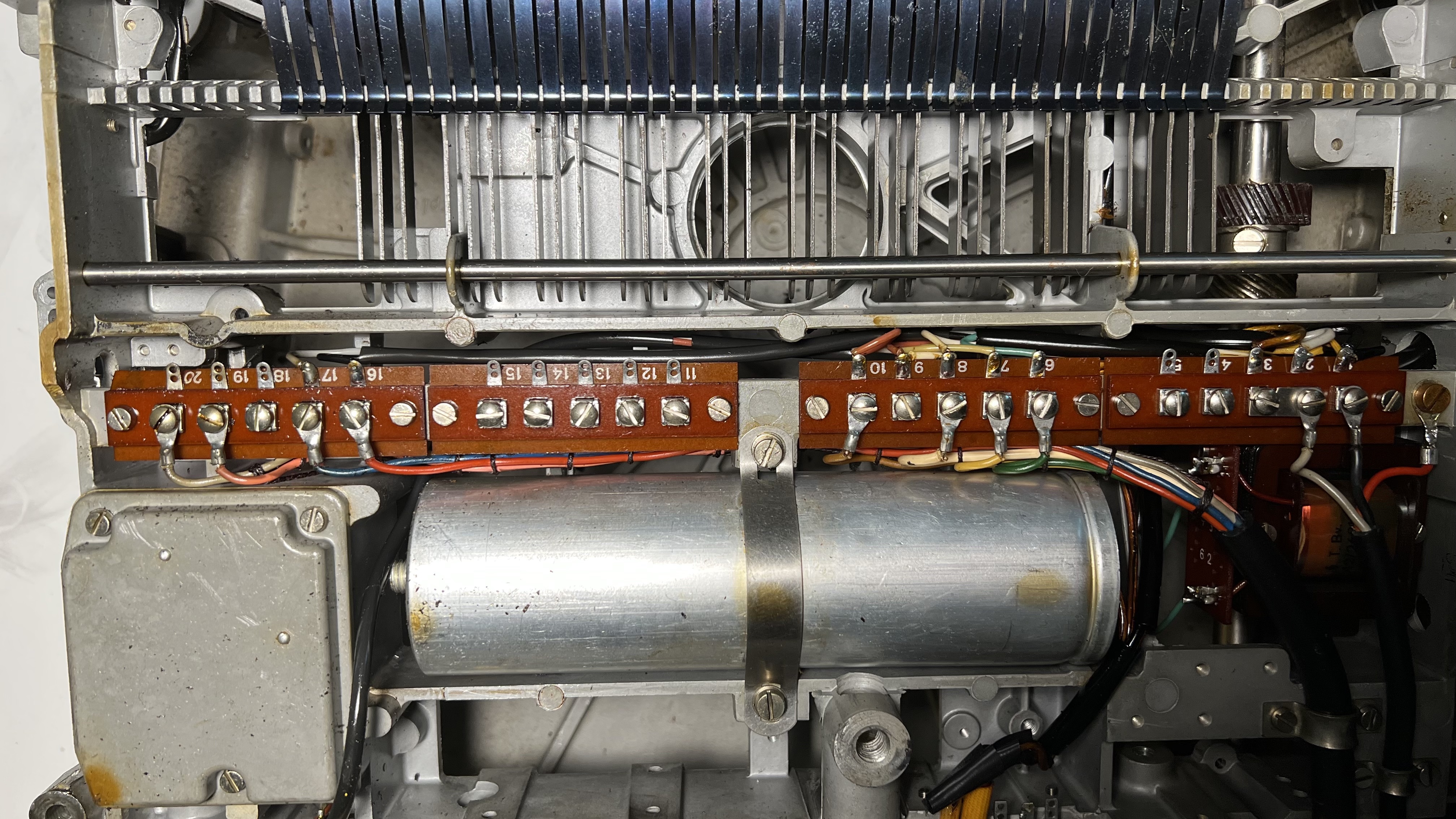
The wiring for this model was confusing. There were wires on the terminal block connected to blades on the connector, but not connected to anything on the teletype. My best guess is Western Union really screwed around with the wiring on this thing. It ended up just needing wiring to the input of the transmitter, the return of the transmitter, the input of the receiver, and the return of the receiver. I had to take it halfway apart and trace out the wiring from the terminal block, but it was really worth it afterwards, as I had a very complete picture of how this model was wired. I believe it was wired as receive-only, after it was originally wired for transmitting and receiving, as the transmitter wire was soldered to a lug with no wire connected to its corresponding screw block (number 9 in the photo). The remaining wires were connected in the expected way presented in the manual. Yellow (lug 7) to the receiver input, green (lug 6) to the receiver return, and brown (lug 10) to the transmitter return.
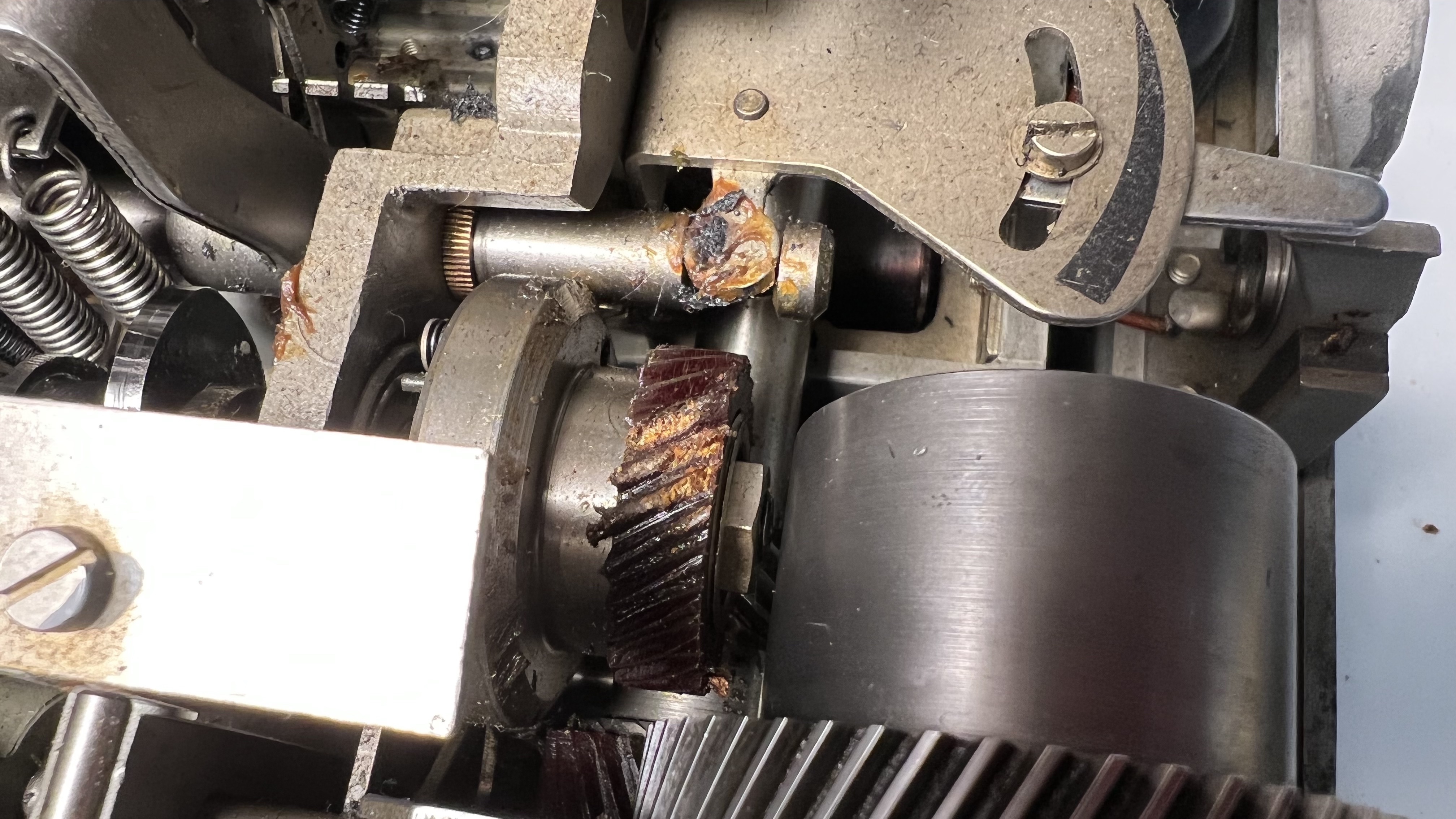
After the first time I was able to run it closed, and able to turn this device into a very complicated typewriter, rather than a doorstop, I got a little greedy and tried the tape puncher. Naturally it jammed and destroyed the clutch gear, which is a composite material made of resin or some other substance and cotton fiber as a substrate. This is intensely displeasing. If I lived in Europe, this part would be difficult to acquire. In the states I just didn't even bother looking that hard.
I managed to design a part in OpenSCAD, 3D print it in PETG, and get the clutch working again. It sounds worse, but it works reliably, and being that it interfaces with a steel helical gear, I know the plastic is softer and won't harm it. Ultimately, I have to assume these composite gears are considered sacrificial in a way, to save the motor and other parts during a jam.
Lesson learned from working on my first teleprinter: When testing the circuit, turn the gears by hand to make sure it turns freely. That said, when I tested with the tape puncher by hand, it spun freely. It wasn't until it was spinning via the motor that it jammed.
I ended up just removing the tape transmitter attachment (the puncher). The tape reader was long-gone, so I had no ability to read them anyhow. At least this way, there's a little less load on the various gears and motor.
Rather than use alligator clips forever, I opted for removing the communications cable from the terminal block on the underside of the chassis, using some hookup wire, crimped connectors for the terminal block, some nylon wire loom, and XT60 connectors to connect the four current loop connections. I also rewired the power cable to use a normal US connector, which was made simpler by the fact the original power connector was connected using screw lugs instead of solder. I thought about going Teletype-style, using 1/4" phono connectors, but the XT60 are good, solid connections, frequently used on 3D printers, and are rated for a healthy amount of both amperage and voltage, and I had plenty of them.
Getting past this device's desire to destroy itself, the next step was a circuit to interface it with a computer. I opted for adapting the circuit designed by Eric Volpe to my needs, using slightly different parts. My repo of changes is here: https://github.com/lysol/usb-tty/. I'd show off pictures of what I ended up putting together, but it's just a protoboard version of the circuit, much less impressive than the completed board on that page.
The previous page linked, as well as This page at teletype.net, detail the way this circuit works. It's not entirely complicated, though the circuit-sensing circuit was a new one for me. The optocoupler receives from the teleprinter, The solid-state relay sends bauds back. I've made a couple of modifications, altering the code to drive a relay for the AC motor, and a relay for the current loop supply. Sending Ctrl-R and Ctrl-T over serial, powers the relays on and off, respectively.
The most difficult part of the circuit was adjusting the current-sensing portion for a 40mA current loop. I had to adjust the resistor values to cause the optocoupler to toggle, so I spent some time in circuitjs until I had the values I needed.
Into the mix I also added a spare Raspberry Pi Zero W, intending to use that as server in front of the serial part of the setup. I'm working on modifying the firmware code to use the built-in UART of the atmega32u4, since that's much simpler than the USB serial bootloader I have flashed to this in the first place, and would save quite a few steps for anyone reproducing this work, since you wouldn't need a new bootloader or any new fuse settings.
I wrote a script that fires up the motor and current loop, and sends the contents of stdin to the teleprinter. Here's a video of me grabbing the current NWS Area Forecast Discussion for my area and printing it as it used to be. The column limits for the text even match up to where they need to be to print correctly on a teleprinter/teletype.